1997 American Dream 2016 09 04
Click picture to see larger one
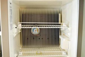
So we went on a trip and had problems with the fins in the refrigerator freezing up.
To be fair, it was very hot and very humid
A fellow racer suggested a product from a company call Smart RV Products https://smartrvproducts.com/
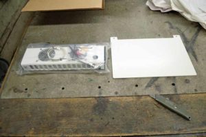
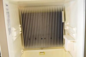
I called them up and talked with them, turns out they make a specific unit for the Dometic RM 7732 side by side refrigerator. The difference between this unit and other offered by Smart RV Products is that there is a skirt provided that directs the fan discharge down across the fins. In the Dometic RM7732, these fins are much longer than in a normal RV refrigerator.
Unit is expensive, but is a complete unit, no fans hanging from the fins.
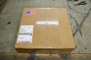
After talking with JC Refrigeration who supplied the new cooling unit for the refrigerator, I ordered one and it has arrived.
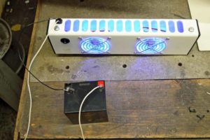 I tested the unit before installing and a nice gentle flow of air is supplied across the entire back of the unit.
First step is to turn off all power to the refrigerator. Then all the racks need to be removed (well not all of them, but I did because I know I will drop something and will have to go searching for it)
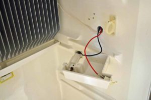
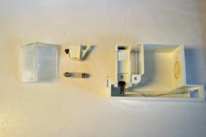
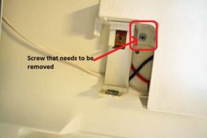 Next I removed the lens on the refrigerator light. Behind the lens is a single screw that hold the housing covering the wires for the light. Power for the fan will be drawn from the light power source. There is no need to drill any holes to run wires. I elected to remove the whole unit as the light has been working interminably. I have discovered that the switch needs to be replaced
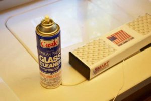 The unit is mounted using Velcro, the directions state to thoroughly dry the top of the refrigerator otherwise the adhesive will not stick. I left the door open for several days to insure the surface was warm and dry and then used glass cleaner to clean the surface
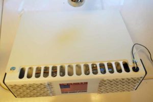 To assemble the unit the two bolts in the back of the unit are removed, The air baffle (skirt) is reversible with a textured surface on one side and a smooth surface on the other. I elected to install the smooth side out for easy cleaning. The skirt is positioned and the bolts are reinstalled snugly, do not over tighten as they used nutserts on the rear of the unit. It would not take much to spin them in their holes
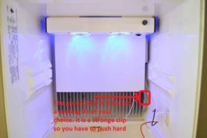 The backing is removed from the Velcro and the unit is carefully placed against the top of the refrigerator and held in place for at least 20 seconds. If you do not get it into the correct location do not worry as you can remove it by separating the Velcro and putting it into the correct position. You will need to install the ground clip for the cooling fan. It is clipped to one of the cooling fins of your choice. The clip is made of high tensile steel, so you will have to push hard
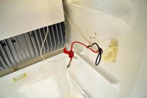 Run the power wire for the fans to the refrigerator light. I ran mine beside the thermistor wire. I ran to Home Depot and got some white wire tires. They supplied black ones and the white ones do not stand out as much. They supply the 3M wire splice. Because of the low current involved here, I did use it
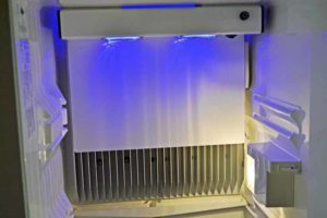 They want you to enlarge the hole the wires come through the refrigerator and push the splice into the hole. When I installed the cooling unit on the back of the refrigerator I sealed this hole. There is plenty of space inside the refrigerator light housing to contain the splice.
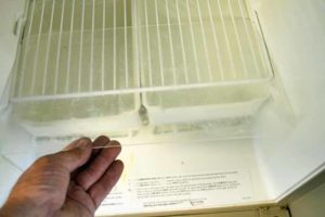 Now it is time to reinstall the racks. The lowest rack has this clear plastic sheet on it, they recommend not putting it back as it impedes air circulation
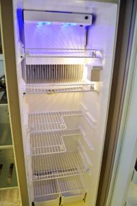 So this is what it looks like now
Let’s talk about air circulation a bit. The original owner picked up some additional bins. Although it is a good way to organize the refrigerator they imped the flow of air if you place them across a shelf. If you use tupperware products, they could do the same thing. If you spread them out so that air can flow top to bottom I think they will be all right, see the left picture below on how not to do it and the right picture on how we will try it.
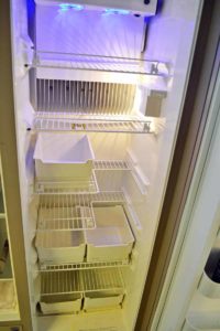
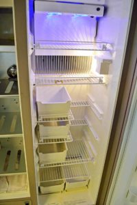
Another concern has been brought to my attention and that is the current load put on the circuit board that controls the refrigerator, which also controls the interior light that the cooling fans draw power from. So a little research says:
In my refrigerator the light says 15 watts is the max wattage allowed. Now that might be for the fixture and not the circuit
The bulb in the fixture says Philips 12 volt 10 watt
So the equation Amps = Watts/Volts says my bulb draws .83 amps and that is only when the door is open
The dual fan unit draws .5 amps
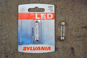
I will replace with an LED
Converting to an LED light means the current draw on the board will be less than the normal incandescent bulb originally drew.
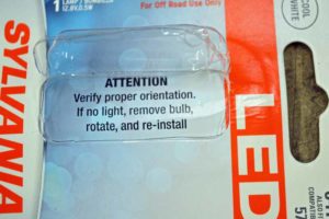 Warning inside the card that contained the LED
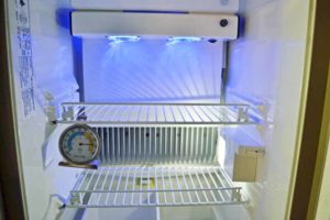 This is the end result, the LED is not as bright as the incandasent bulb was (do not let the picture fool you as the light meter in the camera set the exposure)
I have one more improvement I will be doing and will post that when it is done. I will also let you know how this project works out.
