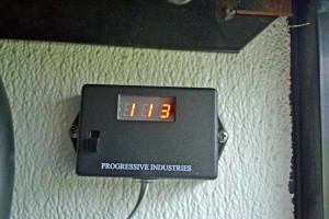
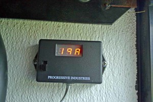
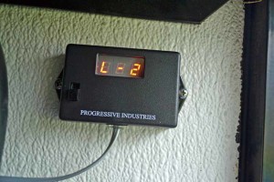
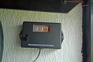
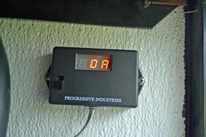
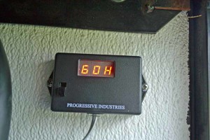
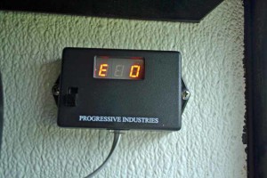
1997 American Dream Surge Protection Voltage Monitor
Click picture to see larger one
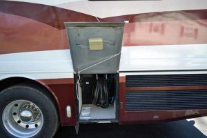
You will have to excuse me on this as some of this text may not run smoothly. I am writing this to go into three different areas (E-mail to personal contacts, Post in the IRV2 Forum, and on my website. So let’s start. Back on 07/11/2015, I was working on the transfer switch. It turned out that the points had some corrosion on them and when I went to run on the generator the transfer switch would not supply the Coach power from the generator. This is detailed in post #585 at this link http://www.irv2.com/forums/f107/projects-on-my-1997-american-dream-174380-42.html#post2644544 We resolved that problem, but found that in the past some Previous Owner had criminally bypassed the surge protector and voltage monitor. Why do I call it criminal? Well, what was done is they spliced the incoming line (shore power) to the cord feeding the transfer switch inside the Surge Protector box. So, without opening the box, what you saw was the Shore Power cord going into the Surge protector box and a cord coming out of the surge protector box going into the transfer switch. Anyone looking into this compartment would assume the Motor Home was protected, when in fact it was not.
The unit was a PLM-50A produced by RV Electronics, which has gone out of business.
That is the background for this update.
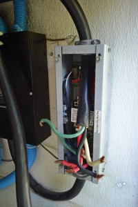
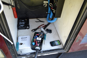
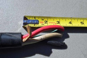
In this picture I have removed the wire nuts that had spliced the incoming Shore Cord to the cord going to the Transfer Switch.
Time to remove this travesty and fix the problem
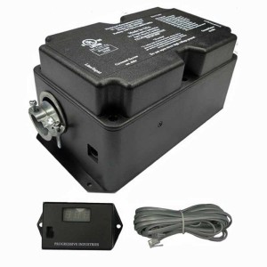
I did some research, asked some questions on the forum IRV2 and the name Progressive Industries http://www.progressiveindustries.net/#!rv-power–surge-hardwired/c1p4w came up a number of times.
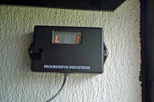
I purchased model EMS-HW50C http://www.progressiveindustries.net/#!ems-hw50c/cjk6 as it came with the remote digital display (along with a number of other functions)
On the display is a switch which will allow you to bypass the unit without having to go inside to “clip the blue wire” . This means you do not have to buy the EMS-ByPass Switch Kit for $24.95
Their web site wanted $410.00 for the unit and Amazon wanted $340.24
I asked if they would match Amazon’s price. Not only would they match but they sold me the unit for $311.00.
It always pays to ask.
The Install
 I found the instructions to be complete and easy to follow. The only hole that I found in them was in the operation instructions. Missing is the explanation of the operation of the bypass switch on the digital display. Nowhere does it tell you functions of the switch (what position is the bypass mode in, Technical support has told me that when in the down position the unit is in the normal operation mode)
http://media.wix.com/ugd/439d5a_cf352e711cf248548185980394ec14a7.pdf
There are instructions for installing the Surge Protector before the Transfer Switch, after the Transfer Switch to protect from both Shore Power and the Generator. There is no option for protecting from surges from the Generator, Shore Power, or the Inverter. I elected to install before the Transfer Switch.
Step 1) Unplug the RV from AC (shore Power), Make sure the inverter is off, and the generator is off.
Step 2) Determine the location for the EMS control box and the digital display.
Step 3) Determine the length of cord needed to reach between the control box and the transferee switch (and then add 6 inches as you will need the extra cord to strip back the insulation on to make your connections (both in the control box and in the transfer switch)
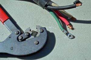
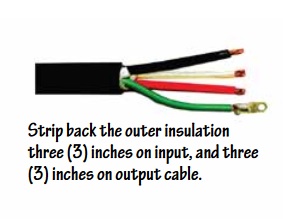
Step 4) Strip back each conductor 3/8 of an inch on both ends (shore power cord and cord that runs between the control box and the Transfer Switch) (I found it necessary to have four inches of leads exposed on the output cable to allow for the sensors to slip over the cable).
Attach the eyelet crimp connector to the green wire (if the green wire is solid core do not use the eyelet connector)
 |
 |
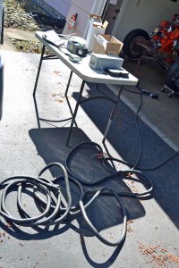
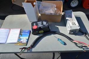
These cords are stiff and heavy. I would set up a table to work on as you want these connections to be good. I clamped the cable to the end of the table to help make working on the cables easier
 |
 |
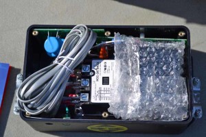 |
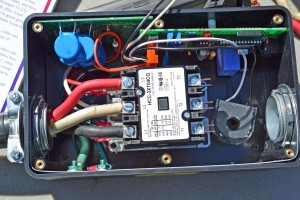
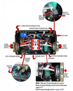
Step 5) Remove the lid from the EMS. Next, remove the display, cable, and the hardware package. Then loosen the six terminal screws L1, L2, L3, T1, T2, and T3 |
Step 6) Take the Shore Power Cord (the one with the plug on the end) and connect it to the input side of the control box by sliding the wire through the wire restraint on the end of the EMS control box. Then connect the ends of the leads to the contactor (magnetic switch) attaching the black lead to L1, white lead to L2, and the red lead to L3.
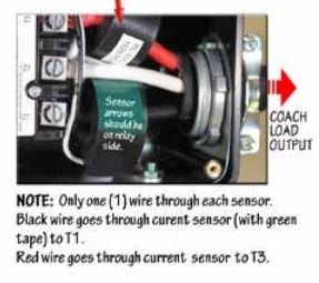
Step 7) Take the short cable you will be using to run between the Surge Protector and the Transfer Switch and slide it through the wire restraint on the EMS control box. Next slide the blck wire through the current sensor with the green tape on it and connect to T1, connect the white wire to T2. Now slide the red wire through the other current sensor and attach to T3.
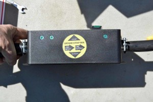 |
The side of the control box is clearly marked as to which end is the line in and which end is the line out |
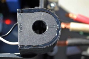
I found it necessary to have these leads longer than what the instructions specified in order to be able to get the current sensors on the lead ends.
Also it is important to have the arrow side off the sensor to face the terminals T1 and T3
 |
 |
Step 8) Double check all connections and make sure they are tight. I have found that with stranded wire you have to go back and tighten connections multiple times before they remain tight.
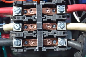 |
Step 9) Remove the two screws on the magnetic switch and remove the cover plate. Examine the inside to make sure there are no loose plastic pieces inside the contactor |
Step 10) Secure the cables running into the control box by tightening the strain reliefs on both the input and output cables, do not over tighten as you may damage the insulation on the cables and cause a short.
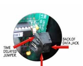 |
Step 11) Set the time delay. I left mine at the factory setting. By removing the jumper you can slow the time delay down to 2 Minutes, 16 seconds. |
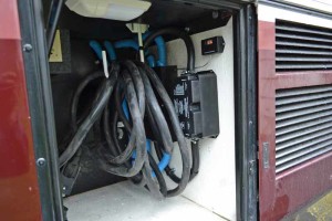
Step 12) Plug in the remote digital display, Step 13) Attach the EMS lid, Step 14) Mount the EMS control box, route the feed cable to the Transfer Switch and secure it
 |
Installation is now complete, plug it in and watch for codes,
………….in my case the unit did not work. That blck cloud just keeps following me everywhere I called technical support |
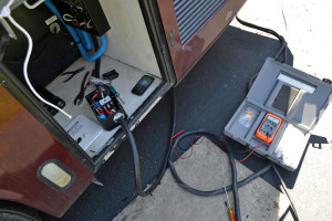
I got Anthony of Progressive Industries (919) 267-6964 on the phone. I pulled the installation all apart and he had me take voltage readings across L1 and L2 (119V) across L2 and L3 (117V) across T1 and T2 (0V) across T2 and T3 (0V). He had me manually hold the Magnetic switch closed and then we got Voltage on the output side, but once released the contactor dropped back out. The Resistance reading across the coil in the Magnetic switch was close to correct, but not correct. The power light on the main board was not lit up. It was decided to send me a new unit as this one seemed to be defective.
So all that is left is to get the bad unit sent back to Progressive Industries, they provide the mailing label. Button everything back up and get started on the window blind project (which has turned into quite a project of its own). I will post an update when it is complete.
Maybe a cord reel is needed to clean up this compartment, we will see.

